8/5/2025
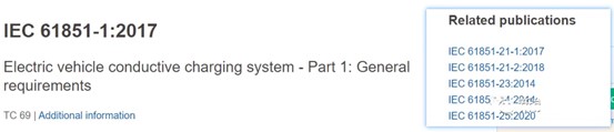
IEC 61851-1. A search on the IEC official website reveals six standards in this series, with the current versions shown below. IEC 61851-1 defines three connection methods and four charging modes:
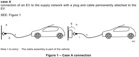
Connection Method A:
In this connection method, the charging
cable is permanently attached to the electric vehicle, and the plug is
connected to the charging network.
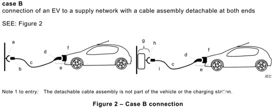
Connection Method B:
In this connection method, the charging cable is detachable from both the electric vehicle and the charging network. The cable is then used to connect the two during charging.
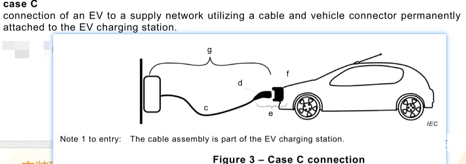
Connection Method C:
This connection method uses a permanently attached charging cable connected to the charging network, and the plug is connected to the electric vehicle during charging.
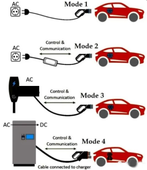
Charging Mode 1:
Mode 1 connects an electric vehicle to a standard AC power network outlet using a cable and plug. Neither is equipped with any supplementary guides or auxiliary contacts; this is known as flying lead charging, which is not permitted under our national standards.
Charging Mode 2:
Mode 2 connects an electric vehicle to a standard AC power network outlet using an AC power supply device. The AC power supply device includes a cable and plug, control and guidance functions, and an electric shock protection system located between the standard plug and the electric vehicle. This involves adding control and guidance circuits to the flying leads.
Charging Mode 3:
Mode 3 connects an electric vehicle to an AC power supply device (permanently connected to the AC power network). This device has control and guidance functions that extend from the AC power supply device to the electric vehicle; this is a typical AC charging method.
Charging Mode 4:
Mode 4 connects an electric vehicle to an AC or DC power network using a DC power supply device. This device has control and guidance functions that extend from the DC power supply device to the electric vehicle; this is a DC charging method.
In summary, the four charging modes are summarized in the figure below.
In addition, the appendix of IEC 61851-1 also defines details such as the charging guidance circuit, which will be discussed later; then look at the relevant standards of IEC 62196. All relevant standards searched on the IEC official website are shown in the figure below. A lot of content was updated in 2022 (IEC TS means that it has not yet formed an international standard and is currently in the technical specification stage).
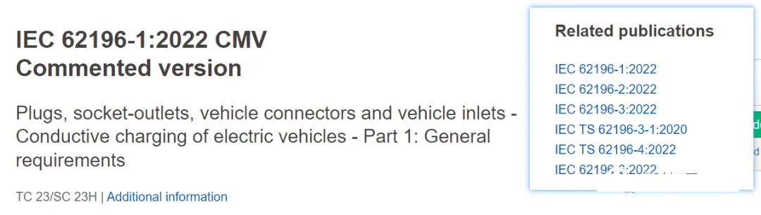
IEC 62196-1 defines all types of interfaces
between electric vehicles and charging equipment. The 2022 version categorizes
interfaces into three types: basic, DC, and combined.
The 2014 version defines four types of
interfaces: basic, DC, combined, and universal, as shown in the figure
below.
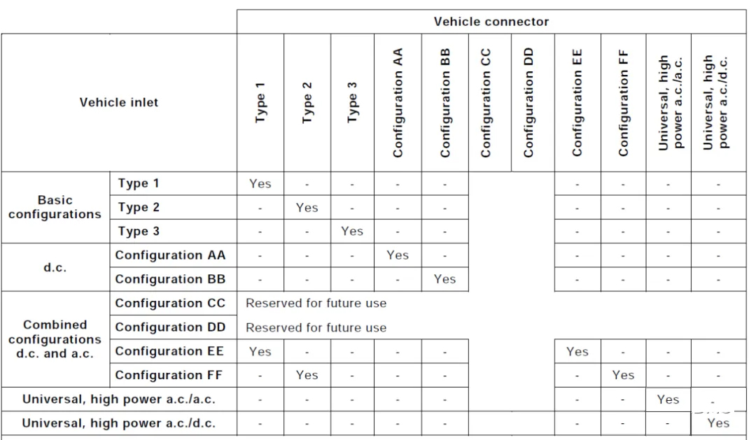
There is an overview of charging interface types in this standard, which are mainly divided into three similar interfaces: basic interface, DC interface and combination interface.
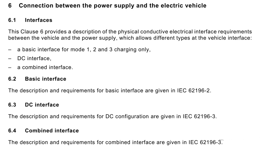
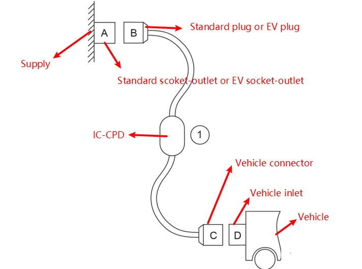
Before the specific introduction, we must
first clarify the following four definitions: EV plug, EV socket-outlet,
Vehicle connector, and Vehicle inlet. The specific diagrams are as follows. You
can see that they represent the names of the connection interfaces between the
power supply equipment end and the electric vehicle end and the wiring harness;
these definitions are involved throughout the standard, so it is necessary to
distinguish them clearly. This division is mainly to match different connection
methods and charging modes. For us, we are more concerned about the Vehicle
connector and Vehicle inlet on the vehicle end, and the two together are called
Vehicle coupler.
IEC 62196-2:2022 mainly introduces the AC
charging interface, namely the Basic interface, which specifically includes
three types of interfaces, namely Type 1, Type 2, and Type 3. The overall
overview is shown in the figure below: It is found that Type 1 only has
single-phase power type, and Type 2 and Type 3 include single-phase and
three-phase power.
Type 1:
Type 1 is a 5-pin connector for single-phase charging. It looks like the following: Note that the vehicle inlet uses pins, while the vehicle connector uses copper tubes. This configuration is inconsistent with my country's charging standards.
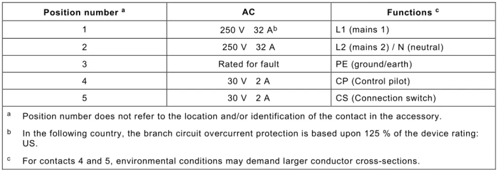
Next, let's take a closer look at the interface definition. The five pins of Type 1 are defined as follows: L1, N, PE, CP, and CS. CP and CS represent the control and guidance functions, respectively, and the vehicle requires full vehicle testing.
Type 2:
The vehicle-side interface defined in Type 2 is shown in the figure below. It is a 7-pin format. Further explanation reveals that there are two types of vehicle-side interfaces, differing structurally in the shape of the central PE port. The more common types are 2-IIe and 2-IIf. The interface definition and structure are identical for both single-phase and three-phase models, and the vehicle inlet also uses pins.
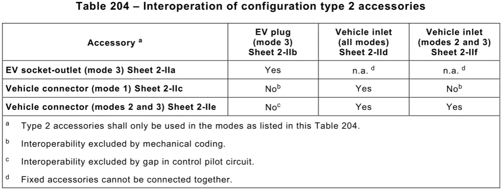
The standard shows that 2-IIc is primarily used for charging mode 1, while 2-IIe and 2-IIf are primarily used for charging modes 2 and 3. 2-IId supports all three modes, as shown in the figure below.
Type 3:
The demand for Type 3 originated in Italy,
but it's rarely seen in real-world applications. Type 3 is divided into three
different connector types based on their electrical properties. Each of these
connectors has distinct structural dimensions and definitions, as shown in the
figure below. They differ significantly from Type 1 and Type 2 in structure.
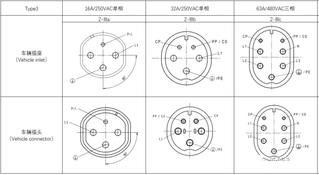
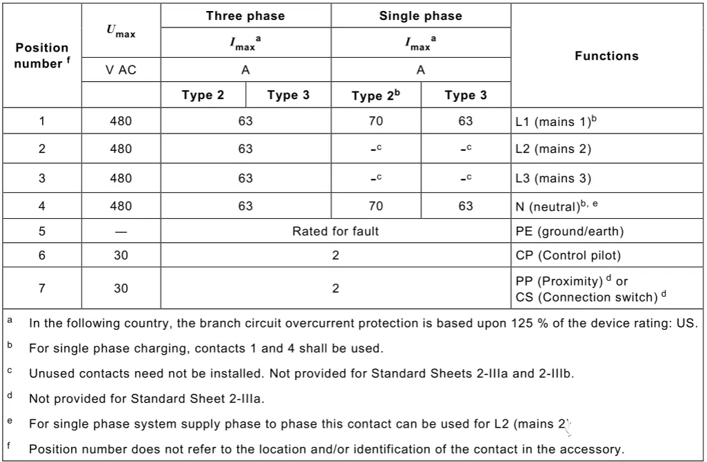
Finally, the interface pin definitions of Type2 and Type3 are as follows. It should be noted that the 2-IIIa charging interface in Type3 has only one control pin CP, without PP or CS.
This standard mainly introduces DC charging
interface and combined charging interface, which add up to four types. The
overview is shown in the figure below. The following are introduced
respectively:
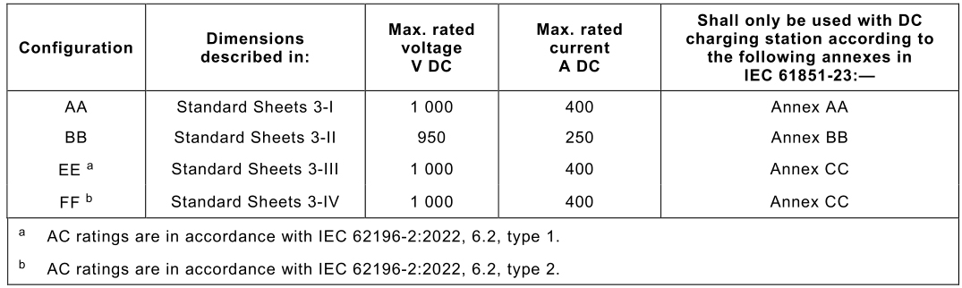
DC Charging Interface
DC charging interfaces are divided into two types: AA and BB. The AA interface, shown in the figure below, has a distinctive shape and features 10 pins, one of which is actually reserved for unused.
The BB interface, also known as the DC charging interface, actually uses 9 pins.
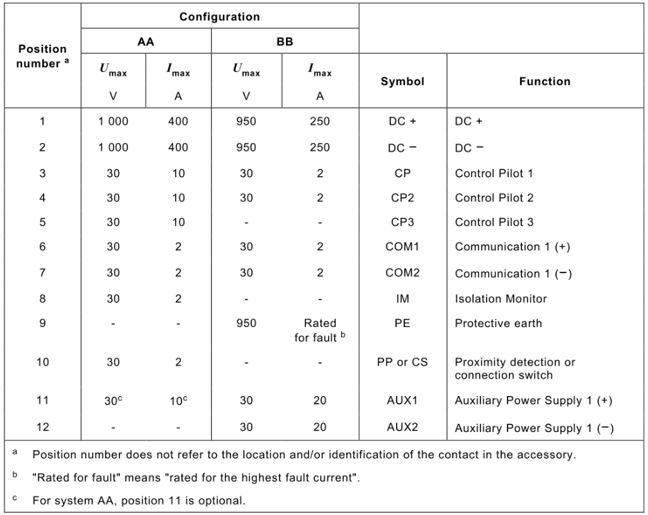
Finally, let's take a look at the interface definitions for these two interfaces, as shown in the figure below. Both the AA and BB DC interfaces have female connectors (copper tubes) on the vehicle's sockets. This aligns with the Chinese charging standard, but contrasts with the previously mentioned IEC AC standard (which uses pins). The IEC standard requires the use of female connectors on the power supply side to prevent electric shock. Also, note that both the AA and BB DC charging interfaces have communication pins, typically for CAN communication.
Combined Charging Interface
Combined charging interfaces are categorized into two types: EE and FF. These interfaces integrate both AC and DC charging into a single interface. The EE type, as shown in the figure below, combines the Type 1 AC charging vehicle inlet and a DC charging interface in IEC 62196-2. Note that this type of AC charging only supports single-phase charging; the EE type vehicle plug only supports DC charging.
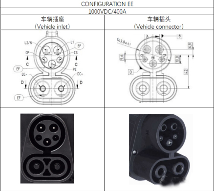
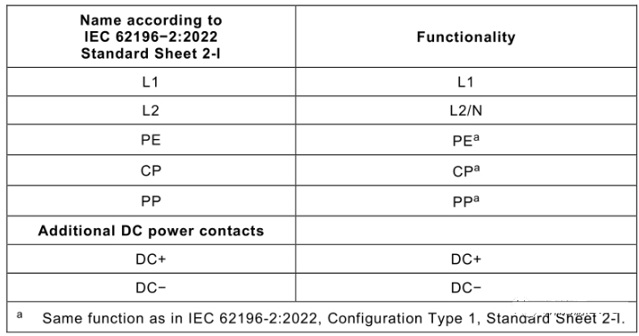
The pin function definition of the EE type
interface is shown in the figure below. There are a total of 7 pins. Since AC
only supports single-phase charging, there are only L1L2; in addition, for DC
charging, you will find that there is no dedicated communication interface.
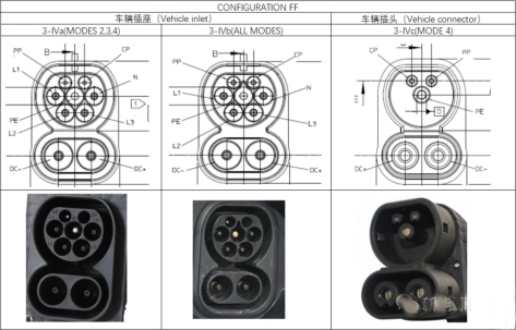
The FF-type combined charging interface,
shown in the figure below, combines the Type 2 AC charging vehicle inlet in IEC
62196-2 with a DC charging interface, supporting both single-phase and
three-phase AC charging. You'll also find two types of FF-type vehicle inlets:
3-IVa and 3-IVb. The former doesn't support charging mode 1, which is in line
with the IEC 62196-2 standard. The 3-IVc vehicle plug only supports DC
charging.
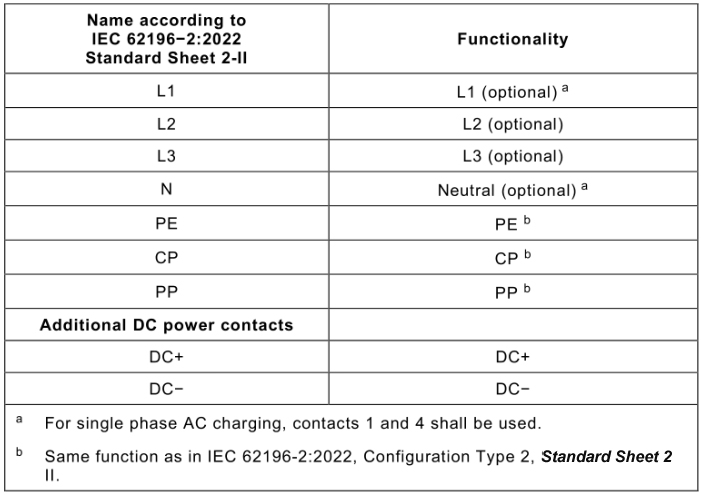
The pin function definition of the FF type
interface is shown in the figure below. There are a total of 9 pins. Compared
with Type 2, it only has a DC charging pin. Similarly, there is no pin
dedicated to communication because it is actually used for PLC communication.
Finally, regarding the combined charging
interface, AC charging and DC charging cannot be performed simultaneously using
the same vehicle plug. In addition, the vehicle plugs covered in this section
are only for DC charging. AC charging requires the AC vehicle plug specified in
IEC 62196-2.
The following are our popular EV charging products that you may be interested in. If you have any questions, please feel free to contact us, and our specialists will answer within 24 hours.
